Series P010
OEM Oscillator/Demodulator
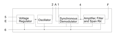
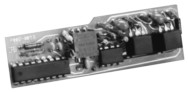
The Series P010 Oscillator/Demodulator PC Boards are the ideal AC LVDT interface for OEM applications. The compact circuit board design includes an ASIC for the oscillation/demodulation function, with peripheral components included for voltage regulation, output scaling and filtering. The synchronous demodulator converts the AC voltages from the secondary coils to a DC voltage, where the output is amplified and filtered. A standardized ±5 VDC output signal is adjustable by manipulating an integral trim pot and can be used as an input to most A/D cards. The small size of this PC Board design makes it ideal for applications where space is limited.
Key Features
- Works with 5 and 6 wire LVDTs
- Internally Regulated
- DC Voltage Output
- Small Size and Low Cost
MODEL
| MODEL | FREQUENCY KHz ±10% | LVDT PHASE ANGLE |
| P010-0031 | 3 | ALL |
| P010-0032 | 7 | > 10 Degrees |
| P010-0033 | 7 | < 10 Degrees |
ELECTRICAL SPECIFICATIONS
| INPUT POWER | Voltage | ±14 to ±28 VDC, Input polarity protected NOTE: DUAL DC OUTPUT POWER SUPPLY REQUIRED |
| Current | ±100 mA Max. plus LVDT current | |
| OSCILLATOR OUTPUT TO LVDT | Voltage | 1.7 VRMS, nominal |
| Current | Will drive LVDTs wth primary impedance > 100 Ohms short circuit protected | |
| SIGNAL OUTPUT | Voltage | Adjustable (via integral multi-turn Span trim pot) to ±5.0 VDC when LVDT is 0.5V/V (±10%) at the end of its linear stroke; Output voltage is linear to ±6.0 VDC and limited to ±8 VDC |
| Current | To ±5 mA without distortion | |
| Impedance | < 2 Ohms | |
| Ripple | ≤ 0.030 VRMS | |
| Frequency Response | 300 Hz (-3 dB Point) | |
| ACCURANCY | Non-linearity | ±0.05% Max. over ±6 VDC output |
| Temp. Coefficient | < ±0.0001 VDC °F ±0.01% output/°F | |
| TEMPERATURE RANGE | Operating | +32°F to +158°F (0°C to +70°C) |
| Storage | -67°F to +257°F (-55°C to +125°C) | |
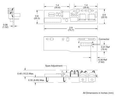
| CONNECTIONS | Double row, 12 socket connector (Berg # 66953-06 or similar). Mates with dual row of 0.025 inch square or round pins on 0.1 inch centers, 0.19 inch to 0.30 inch long. |
DIMENSIONAL DRAWING

CONNECTION & MOUNTING
The Series P010 contains a standard Berg model #66953-06 connector for easy installation on user’s PC Boards. For applications where the electronics will be subject to vibration, it is recommended that the Series P010 board be clamped onto the user’s main PC board assembly.
PINOUT
| PIN | FUNCTION |
| 1 | LVDT Output, Non-Lead End |
| 2 | Oscillator Output High |
| 3 | Not Used |
| 4 | Unfiltered Demodulator Output |
| 5 | -15 VDC Power Supply |
| 6 | Common |
| A | LVDT Output, Lead End |
| B | Not Used |
| C | Not Used |
| D | Not Used |
| E | +15 VDC Power Supply |
| F | Analog Output |
BLOCK DIAGRAM

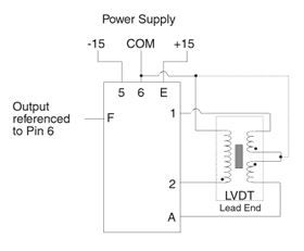
INTERCONNECTION DIAGRAM


