Series 290
General Purpose AC LVDTs
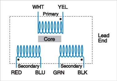
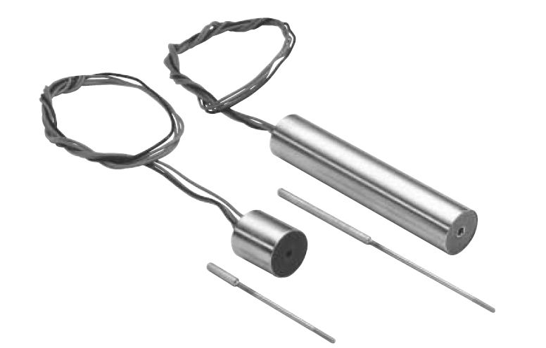
The Series 290 AC LVDTs are general purpose transducers designed to operate in most industrial environments. All units are terminated in 6 leads, allowing convenient connection to most conditioning electronics.
Key Features
- Ranges from ±0.05” to 6.0”
- Non-linearity ≤ 0.5%
- High Input Impedance
- 0.5” and 0.75” Outer Diameter
SPECIFICATIONS - ELECTRICAL
| MODEL | LINEAR RANGE ±Inches (mm) |
REFERENCE FREQUENCY |
SENSITIVITY V/in./V |
INPUT IMPEDANCE Ohms |
OUTPUT IMPEDANCE Ohms |
PHASE ANGLE UNCOMPENSATED |
FREQUENCY FOR ZERO PHASE SHIFT |
MAXIMUM EXCITATION |
| 0290-0000 | 0.050 (1.27) | 10.0 KHz | 2.6 | 1550 | 860 | -3.6° | 7.0 KHz | 1.0 V.A. |
| 0291-0000 | 0.100 (2.54) | 5.0 KHz | 3.9 | 740 | 1790 | 0° | 5.0 KHz | 1.0 V.A. |
| 0292-0000 | 0.250 (6.35) | 2.4 KHz | 1.6 | 2100 | 813 | 9.3° | 30 KHz | 1.0 V.A. |
| 0293-0000 | 0.500 (12.7) | 2.4 KHz | 0.75 | 800 | 156 | 11° | 10 KHz | 1.0 V.A. |
| 0294-0000 | 1.00 (25.4) | 2.4 KHz | 0.61 | 458 | 194 | 9.3° | 9.3 KHz | 1.0 V.A. |
| 0295-0000 | 2.00 (50.8) | 2.4 KHz | 0.41 | 2050 | 520 | 7° | 6.4 KHz | 1.0 V.A. |
| 0296-0000 | 3.00 (76.2) | 2.4 KHz | 0.23 | 1360 | 356 | 14° | 6.8 KHz | 1.0 V.A. |
Notes:
- Electrical specifications are based on energizing the primary coil with the specified excitation frequency.
- Nominal values are given for sensitivity.
- Operating Temperature -50°F to +250°F (-46°C to +121°C)
SPECIFICATIONS - MECHANICAL
| MODEL | HOUSING LENGTH A Inches (mm) |
CORE LENGTH B Inches (mm) |
ELECTRICAL CENTER C Inches (mm) |
INNER SLEEVE MATERIAL |
TOTAL NET WEIGHT W/0 CORE Grams |
CORE NET WEIGHT Grams |
CORE PART NUMBER |
LEAD LENGTH, GAUGE |
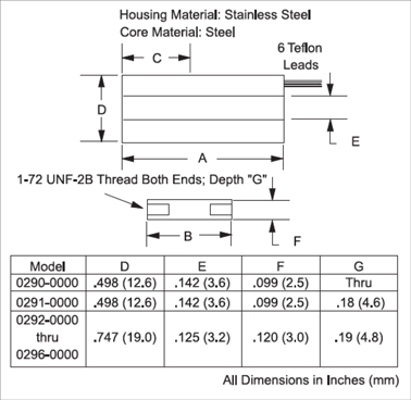
| 0290-0000 | 0.88 (22.3) | 0.56 (14.2) | 0.34 (8.64) | PHENOLIC | 14 | 0.4 | C005-0003 | 7” AWG #30 |
| 0291-0000 | 1.06 (27.0) | 0.81 (20.6) | 0.46 (11.7) | PHENOLIC | 17 | 0.7 | C005-0007 | 7” AWG #30 |
| 0292-0000 | 3.21 (81.5) | 1.75 (44.5) | 1.40 (35.6) | S.S. | 56 | 2.5 | C005-0054 | 18” AWG #26 |
| 0293-0000 | 3.71 (94.2) | 1.50 (38.1) | 1.65 (41.9) | S.S. | 65 | 2.0 | C005-0055 | 18” AWG #26 |
| 0294-0000 | 4.71 (120) | 1.75 (44.5) | 2.15 (54.6) | S.S. | 74 | 2.5 | C005-0054 | 18” AWG #26 |
| 0295-0000 | 8.21 (209) | 2.50 (63.5) | 3.90 (99.1) | S.S. | 116 | 3.6 | C005-0056 | 18” AWG #26 |
| 0296-0000 | 10.52 (267) | 2.00 (50.8) | 5.30 (134) | S.S. | 136 | 2.8 | C005-0048 | 18” AWG #26 |
For technical drawings, and more information please download the Spec Sheet PDF. You will need to have Adobe Reader installed. Please feel free to contact us directly if you need assistance with any of our product specs or require information about non-standard items.
DIMENSIONAL DIAGRAM

SCHEMATIC

CORE EXTENSION RODS (Sold Separately)
The recommended core extension rods are made of nonmagnetic stainless steel and are sized to allow the transducers to operate over their full range. Extension rods from models with longer strokes may be used to facilitate installation. Using extension rods shorter than recommended may reduce the LVDT’s usable measurement range.
| MODEL | LENGTH L (mm) | CORE EXTENSION ROD |
| 0290-0000 | 2.00 (50.8) | C006-0056 |
| 0291-0000 | 2.00 (50.8) | C006-0056 |
| 0292-0000 | 2.00 (50.8) | C006-0056 |
| 0293-0000 | 3.25 (82.6) | C006-0057 |
| 0294-0000 | 5.25 (133) | C006-0058 |
| 0295-0000 | 8.40 (213) | C006-0059 |
| 0296-0000 | 8.40 (213) | C006-0059 |
CAD Drawings
Download drawings from 3DContentCentral.com. (Account Required)
Download Now
RELATED PRODUCTS AND ACCESSORIES
- Core Extension Rods
- Mounting Clamps


