
The Trans-Tek Series 100 Linear Velocity Transducers produce a DC output voltage proportional to the velocity of the magnet relative to the coil. These units are designed and tested to assure that they conform to prescribed specifications. Each unit is calibrated by our QC Dept., and a strip chart recording of the results are packaged with each unit.
The items used to conduct a typical calibration are: Strip Chart Recorder, High-Resolution DC Voltage Reference, Digital Volt Meter, and a proprietary Velocity Calibration Stand. The velocity stand provides a constant velocity, moving the magnet relative to the coil at typically 50 mm/sec. The DC output voltage generated from the transducer is recorded on a strip chart. Computation of the unit’s sensitivity and conformance to accuracy requirements can be made from this data.
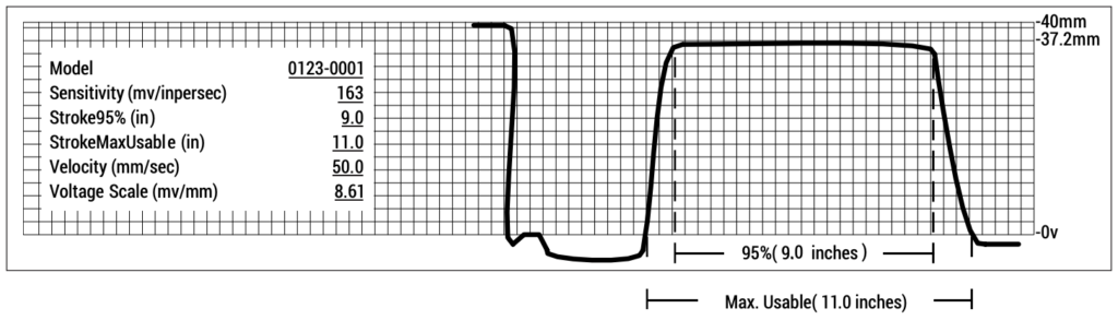
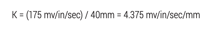
The strip chart recorder is initialized by applying a calculated DC voltage from a high-resolution voltage source. This calibration voltage is determined for each model LVT. To calculate the correct input voltage, a maximum allowed sensitivity must be selected. The strip chart example shown above is for Model 0123-0001, whose maximum sensitivity is 175 mv/in/ sec (this is a design parameter for that model). Since the strip chart paper will record over a height of 40mm, a multiplication factor is generated. For Model 0123-0001, the multiplication factor is:
The formula for voltage input is:

Solving for Vin yields 0.3445 VDC, which is the voltage applied to the recorder for the Model 0123-0001. Since this is the maximum voltage the strip chart recorder will now record, dividing by 40mm yields the Voltage Scale value for the strip chart, which in this example is 8.61 mv/mm.
The system is automated so that once the magnet and coils are properly fixtured, a switch is engaged to start the calibration procedure. The calibration starts with the magnet outside the coils. The voltage recorded steadily increases until both poles of the magnet are within the working range of the coils. At this point, the voltage output stabilizes at the sensitivity of the transducer. In this example, the voltage output in the working range of the LVT is recorded at an average of 37.2 mm (there is some ripple shown on an actual calibration report). Since we already know the multiplication factor K = 4.375 mv/in/sec/mm, we can multiply this by 37.2 mm, yielding 162.75 mv/in/sec. This is rounded to the nearest whole number, in this case 163 mv/in/sec.
These transducers are specified to be accurate within 5% of the average sensitivity. As long as no point over the stabilized output exceeds 5% of the sensitivity, the unit will be accepted within the accuracy specification.