LVDT Technology
What is An LVDT?
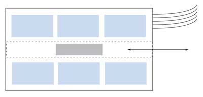
An LVDT, or linear variable differential transformer, is a type of electrical transformer used to measure linear displacement (or position). They are also known as LVDT sensors. An LVDT consists of a primary coil, a movable core, and two secondary coils. The primary coil is connected to an alternating current (AC) power source, and the secondary coils are connected to a measurement device such as a bridge circuit. As the core moves in or out of the transformer, the relative inductance between the primary coil and each secondary coil changes, causing a change in the output voltage of the secondary coils. This change in voltage can be used to determine the displacement of the core.
LVDTs are commonly used in industrial applications such as measuring the position of valves, pistons, and other mechanical components just name a few. They are highly accurate and have a wide measurement range.
What Does an LVDT Measure?
An LVDT can be used to measure the linear displacement of a wide range of objects, across many different industries. Here are some typical LVDT applications:
- Machine Tooling – LVDTs are commonly used in machine tools to measure the position of slides, tables, and other moving parts.
- Industrial Process Control – LVDTs are used in process control systems to measure the position of valves, pumps, and other equipment.
- Aerospace – LVDTs are used to measure the displacement of various components in aerospace applications such as aircraft flap and landing gear position.
- Automotive – LVDTs are used to measure the displacement of various components in automotive applications such as engine valves and gearboxes.
- Robotics – LVDTs can be used to measure the position of robotic arms and other moving parts in industrial robots.
- Research and Development – LVDTs are used in many research and development settings, such as measuring the displacement of materials in materials testing and measuring the position of components in test stands.
It’s worth noting that LVDT’s are used when linear measurements are needed, other types of sensors like encoders, resolvers, potentiometers and others might be more suitable depending on the application.
How Do LVDTs Work?
An LVDT typically measures displacement relative to an axis. The core of the LVDT is the moving part that is in contact with the object whose position is being measured, and it is designed to move along a specific axis. The position of the core relative to the axis is directly proportional to the electrical signal produced by the LVDT.
In most LVDT’s, there are three coils: a primary coil and two secondary coils. The primary coil is connected to an alternating current (AC) source, and the two secondary coils are connected in series opposition. When the core is in a neutral position, the induced voltage in the two secondary coils is equal and opposite, resulting in no net voltage output. When the core moves in one direction, the induced voltage in one of the secondary coils increases while the other decreases, resulting in a net voltage output that is proportional to the displacement of the core.
LVDT’s are often used in applications where high accuracy and stability are required, and they are not affected by temperature variations, electromagnetic interference, or other environmental factors. They are also relatively insensitive to external vibrations and mechanical shocks, making them suitable for use in harsh industrial environments.
The Null Position
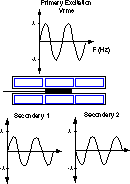 When the physical center of the core is in line with the electrical center of the coils, the voltage in each secondary is equal in magnitude, but opposite in phase. Differencing the two secondary voltages results in “zero” output volts. This is the null position of the LVDT.
In reality, there is a small residual voltage left due to factors like winding capacitance and variances in the magnetic materials. Internal or external signal conditioning electronics compensate for this residual voltage, producing a true electrical zero output.
Direction Sensing
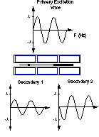
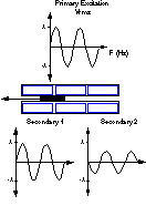 An LVDT is designed to have symmetric measurement ranges on each side of null. As the core moves to one side of the null position, the magnitude of one secondary becomes greater than the other. Differencing the two secondary voltages results in a voltage proportional to the core’s distance from null. The phase of this voltage tells us which side of null the core is on.
DC-DC LVDT Operation
Signal conditioning is an important consideration when designing an LVDT into an application. Converting the AC output voltage of the secondaries into a usable DC output voltage requires a demodulator and low pass filtering. Design of the circuitry must take into account frequency response and electrical noise considerations. For convenience and ease of use, Trans-Tek manufactures a complete line of DC-DC LVDTs, also known as DCDTs, containing an integral oscillator/demodulator.
Discrete components make up the integral signal conditioner. The oscillator converts the DC voltage input to a high frequency AC voltage, powering the primary coil. A passive demodulator rectifies and differences the AC voltage output from the secondaries before filtering the signal with a low pass RC filter. The magnitude and polarity of the DC output voltage are dependent on the position of the core relative to the null position.
Trans-Tek’s DC LVDTs are input polarity protected, meaning that polarity of the input leads must be observed for proper operation, but the unit will not be damaged by polarity reversal. The DC voltage input can range from 6 to 28 VDC, and must be regulated for best accuracy. The magnitude of the output voltage is controlled by the input voltage. These DC LVDTs also feature input and output circuits isolated both from each other and the coil housing. The result is a transducer which can be used in a floating or ground return system.
The LVDTs We Make
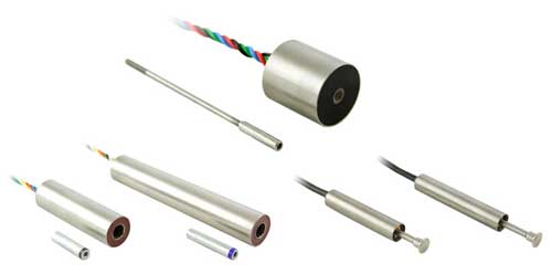
Trans-Tek designs and manufactures a broad line of linear displacement transducers using LVDT technology. An LVDT, or Linear Variable Differential Transformer, is an inductive device containing primary and secondary coaxial wound coils, and a ferromagnetic core. Exciting the primary coil with an AC voltage generates an electromagnetic field. The core links the electromagnetic field of the primary coil to the secondary coils, inducing a voltage in each. The secondary coils are typically wired in series opposition, producing AC voltages 180 degrees out of phase with each other. The magnitude of the voltage in each secondary depends on the position of the core relative to the coils.