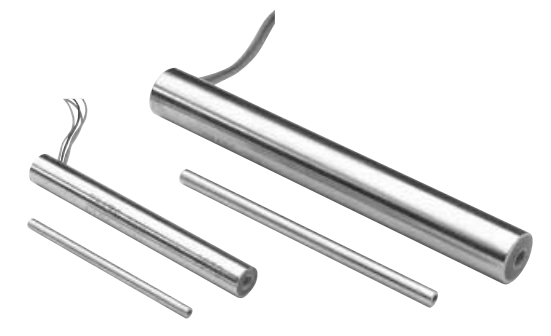
The Series 100 Linear Velocity Transducers provide a simple yet accurate means of measuring linear velocity. They consist of high coercive force permanent magnet cores which induce sizable DC voltage while moving concentrically within shielded coils. The basic design permits operation without external excitation while the generated output voltage varies linearly with core (magnet) velocity. These transducers are ideal for seismology, hydraulic ram speed, drilling rate, and any other application where an instantaneous velocity measurement is required.
| | MAGNET DIMENSIONS Inches | NOM. OUTPUT SENSITIVITY mV/in/sec (mV/mm/sec) | ELECTRICAL IMPEDANCE Coils Connected in Series | REPLACEMENT MAGNETS | FREQUENCY RESPONSE* | |||||||||||
|---|---|---|---|---|---|---|---|---|---|---|---|---|---|---|---|---|
| MODELNUMBER | WORKING RANGE | USABLE RANGE | Open Circuit | R Ohms | L Henries | Magnet Number | Load = 10R | Load = 100R | ||||||||
| 0100-0000 | 0.5 (12) | 1.3 (33) | 120 (5) | 2000 | 0.085 | M000-0000 | 350 | 1500 | ||||||||
| 0100-0001 | 0.5 (12) | 1.3 (33) | 54 (2) | 2000 | 0.085 | M000-0008 | 350 | 1500 | ||||||||
| 0101-0000 | 1.0 (25) | 1.9 (48) | 90 (4) | 2500 | 0.065 | M000-0001 | 600 | 1500 | ||||||||
| 0101-0001 | 1.0 (25) | 1.9 (48) | 40 (2) | 2500 | 0.065 | M000-0009 | 600 | 1500 | ||||||||
| 0111-0000 | 1.0 (25) | 2.3 (58) | 550 (22) | 13000 | 1.6 | M000-0002 | 120 | 600 | ||||||||
| 0111-0001 | 1.0 (25) | 2.3 (58) | 250 (10) | 13000 | 1.6 | M000-0010 | 120 | 600 | ||||||||
| 0112-0000 | 2.0 (50) | 3.4 (86) | 550 (22) | 19000 | 2.9 | M000-0003 | 100 | 500 | ||||||||
| 0112-0001 | 2.0 (50) | 3.4 (86) | 250 (10) | 19000 | 2.9 | M000-0011 | 100 | 500 | ||||||||
| 0113-0000 | 3.0 (75) | 4.2 (107) | 550 (22) | 25000 | 3.2 | M000-0004 | 120 | 500 | ||||||||
| 0113-0001 | 3.0 (75) | 4.2 (107) | 250 (10) | 25000 | 3.2 | M000-0012 | 120 | 500 | ||||||||
| 0114-0000 | 4.0 (100) | 5.5 (140) | 550 (22) | 32000 | 4 | M000-0005 | 120 | 400 | ||||||||
| 0114-0001 | 4.0 (100) | 5.5 (140) | 250 (10) | 32000 | 4 | M000-0013 | 120 | 400 | ||||||||
| 0122-0001 | 6.0 (150) | 8.0 (203) | 160 (6) | 11500 | 1.9 | M000-0014 | 95 | 450 | ||||||||
| 0123-0001 | 9.0 (225) | 11.0 (279) | 160 (6) | 17000 | 2.8 | M000-0015 | 95 | 450 | ||||||||
| 0124-0001 | 12.0 (300) | 15.0 (381) | 175 (7) | 22000 | 3.7 | M000-0023 | 95 | 450 | ||||||||
| 0125-0001 | 16.5 (412) | 18.5 (470) | 175 (7) | 29000 | 5.1 | M000-0024 | 90 | 430 | ||||||||
| 0126-0001 | 20.0 (500) | 22.0 (559) | 175 (7) | 34000 | 6.2 | M000-0025 | 90 | 430 | ||||||||
| 0127-0001 | 24.0 (600) | 26.0 (660) | 175 (7) | 42000 | 7.3 | M000-0028 | 90 | 430 | ||||||||
| 0128-0001 | 28.0 (711) | 30.0 (762) | 150 (6) | M000-0029 | ||||||||||||
| 0129-0001 | 36.0 (914) | 38.0 (965) | 170 (7) | 60500 | 6.1 | M000-0040 | 90 | 300 | ||||||||
| Operating Temperature Range: -50°F to +200°F (-46°C to +93°C) | ||||||||||||||||
| Max. Non-Linearity: <±2.5% of Reading, model 0129-0001 ±5% of Reading | ||||||||||||||||
* Output voltage is attenuated < 1% of the constant velocity value.
NOTE: Polarity of Output: Voltage at Red lead is positive with respect to that at Black when north pole of magnet is closest to, and traveling towards, lead end of LVT.
| | COIL HOUSING DIMENSIONS Inches (mm) | MAGNET DIMENSIONS Inches (mm) | ||||||||||||||
|---|---|---|---|---|---|---|---|---|---|---|---|---|---|---|---|---|
| MODEL NUMBER | CA | LA | (OD)A | (ID)A | WEIGHT WA Grams | LC | (OD)C | THREAD | WEIGHT WC Grams | |||||||
| 0100-0000 | 1.34 (34) | 3.17 (81) | 0.374 (9.5) | 0.13 (3.3) | 20 | 2.38 (60) | 0.125 (3.2) | 1-72 NF | 3.5 | |||||||
| 0100-0001 | 1.34 (34) | 3.17 (81) | 0.374 (9.5) | 0.13 (3.3) | 20 | 1.63 (41) | 0.125 (3.2) | 1-72 NF | 2.5 | |||||||
| 0101-0000 | 1.88 (48) | 4.24 (108) | 0.374 (9.5) | 0.13 (3.3) | 25 | 3.00 (76) | 0.125 (3.2) | 1-72 NF | 4.5 | |||||||
| 0101-0001 | 1.88 (48) | 4.24 (108) | 0.374 (9.5) | 0.13 (3.3) | 25 | 2.25 (57) | 0.125 (3.2) | 1-72 NF | 3.8 | |||||||
| 0111-0000 | 2.25 (57) | 5.06 (129) | 0.624 (15.9) | 0.19 (4.8) | 110 | 3.50 (89) | 0.187 (4.8) | 4-40 NC | 11 | |||||||
| 0111-0001 | 2.25 (57) | 5.06 (129) | 0.624 (15.9) | 0.19 (4.8) | 110 | 2.75 (70) | 0.187 (4.8) | 4-40 NC | 10 | |||||||
| 0112-0000 | 3.25 (83) | 7.06 (179) | 0.624 (15.9) | 0.19 (4.8) | 150 | 4.50 (114) | 0.187 (4.8) | 4-40 NC | 15 | |||||||
| 0112-0001 | 3.25 (83) | 7.06 (179) | 0.624 (15.9) | 0.19 (4.8) | 150 | 3.75 (95) | 0.187 (4.8) | 4-40 NC | 14 | |||||||
| 0113-0000 | 4.25 (108) | 9.06 (230) | 0.624 (15.9) | 0.19 (4.8) | 200 | 5.25 (133) | 0.187 (4.8) | 4-40 NC | 17 | |||||||
| 0113-0001 | 4.25 (108) | 9.06 (230) | 0.624 (15.9) | 0.19 (4.8) | 200 | 4.50 (114) | 0.187 (4.8) | 4-40 NC | 16 | |||||||
| 0114-0000 | 5.38 (137) | 11.31 (287) | 0.624 (15.9) | 0.19 (4.8) | 240 | 6.75 (171) | 0.187 (4.8) | 4-40 NC | 22 | |||||||
| 0114-0001 | 5.38 (137) | 11.31 (287) | 0.624 (15.9) | 0.19 (4.8) | 240 | 6.00 (152) | 0.187 (4.8) | 4-40 NC | 21 | |||||||
| 0122-0001 | 7.63 (194) | 15.81 (402) | 0.749 (19) | 0.30 (7.6) | 420 | 8.50 (216) | 0.23 (5.8) | 4-40 NC | 51 | |||||||
| 0123-0001 | 11.1 (282) | 22.81 (579) | 0.749 (19) | 0.30 (7.6) | 610 | 11.00 (279) | 0.23 (5.8) | 4-40 NC | 66 | |||||||
| 0124-0001 | 14.1 (358) | 29.00 (737) | 0.749 (19) | 0.30 (7.6) | 810 | 14.25 (362) | 0.23 (5.8) | 4-40 NC | 88 | |||||||
| 0125-0001 | 18.6 (472) | 38.00 (965) | 0.749 (19) | 0.30 (7.6) | 1120 | 18.75 (476) | 0.23 (5.8) | 4-40 NC | 121 | |||||||
| 0126-0001 | 22.1 (561) | 45.00 (1143) | 0.749 (19) | 0.30 (7.6) | 1360 | 22.25 (565) | 0.23 (5.8) | 4-40 NC | 147 | |||||||
| 0127-0001 | 26.1 (663) | 53.00 (1346) | 0.749 (19) | 0.30 (7.6) | 1520 | 26.25 (667) | 0.23 (5.8) | 4-40 NC | 156 | |||||||
| 0128-0001 | 30.12 (765) | 61.00 (1549) | 0.749 (19) | 0.30 (7.6) | 30.25 (768) | 0.23 (5.8) | 4-40 NC | 177 | ||||||||
| 0129-0001 | 37.9 (963) | 77.00 (1956) | 0.75 (19) | 0.29 (7.4) | 2200 | 38.25 (972) | 0.23 (5.8) | 4-40 NC | 230 | |||||||
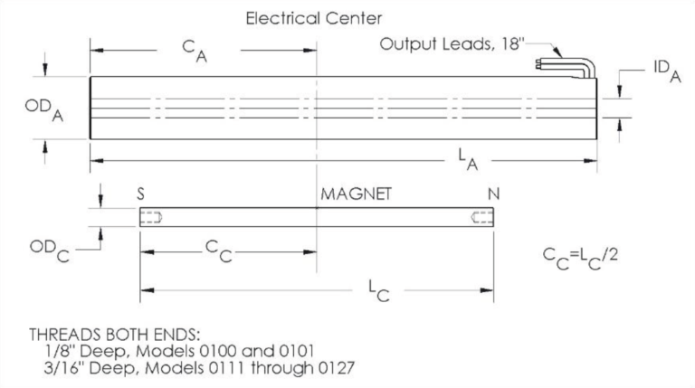
Unlike LVDTs, these transducers do not produce a voltage output unless the magnet is moving. This makes it impossible to electrically identify the correct location of the magnet for linear operation. Users must mechanically position the magnet in the LVT at a known reference point.
As shown in the Dimensional Drawing, the location of the electrical center of the coils is known, and can be used as a reference point. The midpoint of the linear stroke is found by aligning the center of the magnet, CC, with the electrical center, CA, of the coils. Once in position, the magnet can be moved ½ the linear range in either direction.
The transducer housing can be secured with a split block or clamping arrangement. The use of set screws should be avoided, as this may cause internal damage if overtightened.