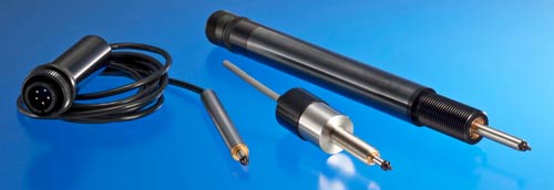
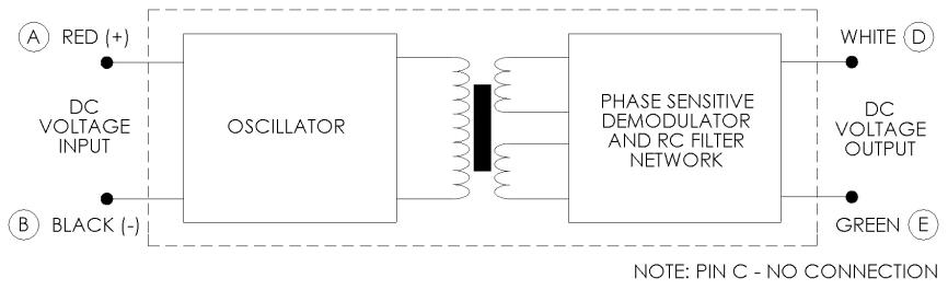
The Series 350 DC Gaging Transducers are an integrated package consisting of a spring-loaded spindle, precision linear variable differential transformer, a solid state oscillator, and a phase-sensitive demodulator. The transducer is designed for excellent linearity, infinite resolution, and high sensitivity. Input and output circuits are electrically isolated from each other and from the coil assembly housing, making them usable directly in floating or ground return systems. DC indicators, recorders, and control systems can usually be driven directly by the large DC output. The spindle, when displaced axially within the coil assembly, produces a voltage change in the output directly proportional to the displacement.
| SPECIFICATION | 0350-0000 | 0350-0010 | 0351-0000 | 0351-0006 | 0352-0000 | 0353-0000 | 0354-0000 | 0355-0000 | 0356-0000 | ||||||||
|---|---|---|---|---|---|---|---|---|---|---|---|---|---|---|---|---|---|
| WORKING RANGE ± Inches (mm) | 0.050 (1.27) | 0.050 (1.27) | 0.10 (2.54) | 0.10 (2.54) | 0.25 (6.35) | 0.50 (12.7) | 1.00 (25.4) | 2.00 (50.8) | 3.00 (76.2) | ||||||||
| MECH. TRAVEL Inches (mm) | 0.16 (4.06) | 0.14 (3.56) | 0.31 (7.87) | 0.31 (7.87) | 0.75 (19.1) | 1.25 (31.8) | 2.25 (57.2) | 4.25 (108) | 6.25 (159) | ||||||||
| INPUT VDC | 6.0 Min. to 28 Max. | ||||||||||||||||
| NOMINAL F.S. OUTPUT @ 6 VOLT INPUT ±VDC | 1.2 | 1.2 | 2.1 | 2.0 | 1.6 | 3.0 | 4.3 | 4.0 | 3.1 | ||||||||
| NOMINAL F.S. OUTPUT @ 15 VOLT INPUT ±VDC | 3.0 | 3.0 | 5.4 | 5.8 | 4.2 | 7.5 | 10.8 | 10.0 | 7.8 | ||||||||
| NOMINAL F.S. OUTPUT @ 24 VOLT INPUT ±VDC | 5.0 | 5.0 | 9.0 | 9.4 | 7.0 | 12.5 | 18.0 | 16.0 | 13.0 | ||||||||
| NOMINAL F.S. OUTPUT @ 28 VOLT INPUT ±VDC | 5.6 | 5.8 | 10.1 | 10.4 | 7.9 | 14.0 | 20.3 | 18.7 | 14.6 | ||||||||
| INPUT CURRENT | 6.3 mA @ 6 Volt input to 48 mA @ 28 Volt input | ||||||||||||||||
| LINEARITY % FULL SCALE OVER TOTAL WORKING RANGE | ±0.50 | ||||||||||||||||
| INTERNAL CARRIER FREQ. Hz NOM. GREATER THAN | 13000 | 13000 | 12000 | 14000 | 3600 | 3400 | 3200 | 1500 | 1400 | ||||||||
| % RIPPLE (RMS) NOM. | 0.7 | 0.7 | 0.7 | 0.7 | 0.8 | 0.8 | 0.8 | 1.0 | 1.0 | ||||||||
| OUTPUT IMPEDANCE Ohms | 2500 | 2500 | 3500 | 3500 | 5200 | 5500 | 5600 | 5500 | 5600 | ||||||||
| TEMPERATURE RANGE | -65°F to +200°F (-54°C to +93°C) | ||||||||||||||||
| RESOLUTION | Infinite | ||||||||||||||||
NOTES:
1. Polarity of excitation must be observed for proper function. Reversal will not damage the unit.
2. Load impedance of 50 KOhms minimum required for proper operation.
3. Output polarity will be positive on one side of null, negative on the other side of null.
4. Transducers are calibrated at 24 VDC.
5. White lead is more positive with respect to the Green lead when the core is moved toward the lead end.
| SPECIFICATION | UNITS | 0350-0000 | 0350-0010 | 0351-0000 | 0351-0006 | 0352-0000 | 0353-0000 | 0354-0000 | 0355-0000 | 0356-0000 |
|---|---|---|---|---|---|---|---|---|---|---|
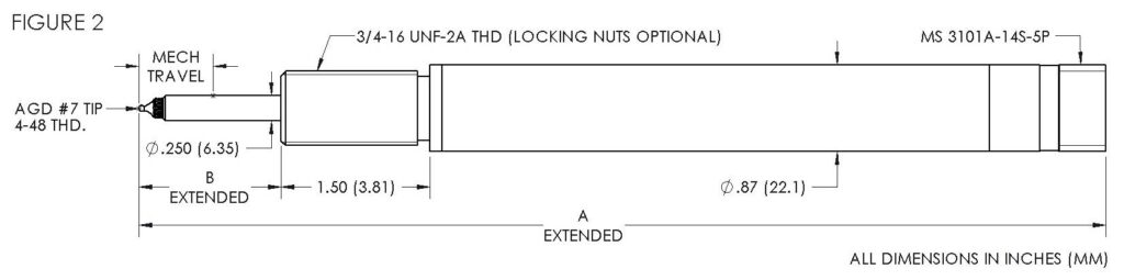
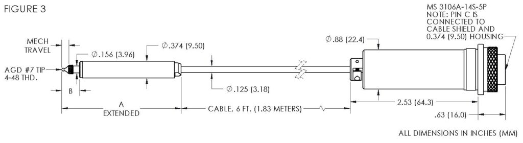
| FIGURE # | 1 | 3 | 1 | 3 | 2 | 2 | 2 | 2 | 2 | |
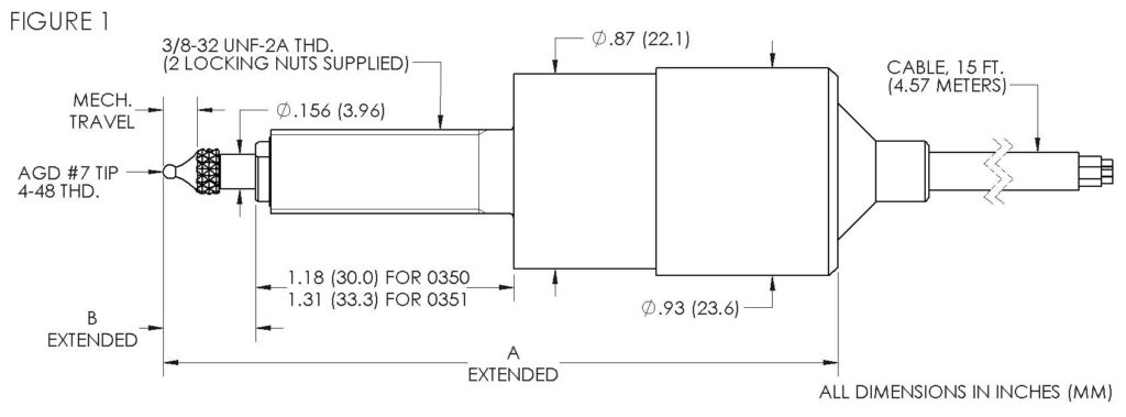
| TOTAL LENGTH A | Inches (mm) | 3.01 (76.5) | 2.63 (66.8) | 3.52 (89.4) | 3.74 (95.0) | 9.89 (251) | 10.89 (277) | 15.31 (389) | 25.43 (646) | 35.02 (890) |
| SHAFT EXTENSION B | Inches (mm) | 0.41 (10.4) | 0.39 (9.91) | 0.56 (14.2) | 0.56 (14.2) | 1.42 (36.1) | 1.42 (36.1) | 2.42 (61.5) | 4.75 (121) | 6.75 (172) |
| TIP FORCE MAX | Grams | 57 | 57 | 170 | 85 | 312 | 425 | 482 | 1276 | 1361 |
| WEIGHT | Grams | 200 | 104 | 207 | 125 | 239 | 275 | 372 | 625 | 845 |
| PART NUMBER | DESCRIPTION |
|---|---|
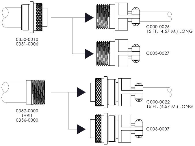
| C003-0007 | Mating Connector Assembly: Connector MS3106A-14S-5S (mates with MS3101A-14S-5P), Cable clamp, and Strain Relief |
| C000-0022 | Cable Assembly: 15 feet of 4 conductor, 22 AWG vinyl cable terminated with C003-0007. (Note: Operating temperature for cable is -22°F to +176°F); Color Code: A – Red, B – Black, D – White, E – Green |
| C003-0027 | Mating Connector Assembly: Connector MS3101A-14S-5S (mates with MS3106A-14S-5P), Cable clamp, and Strain Relief |
| C000-0026 | Cable Assembly: 15 feet of 4 conductor, 22 AWG vinyl cable terminated with C003-0027. (Note: Operating temperature for cable is -22°F to +176°F); Color Code: A – Red, B – Black, D – White, E – Green |
| G000-0000 | Replacement AGD #7 Gaging Tip. (Included with transducer) |
| N001-0025 | 3/4 X 16 UNF-1B Hex Jam Nut |
| Option # | DESCRIPTION | |
|---|---|---|
| X0027 | Reverse spring; spring will be in retracted position. Applies to Models 0350-0000, 0350-0010, 0351-0000 and 0351-0006. | |
| X0031 | Special length interconnecting cable (10 FT. Max.). Applies to Models 0350-0010 and 0351-0006. | |
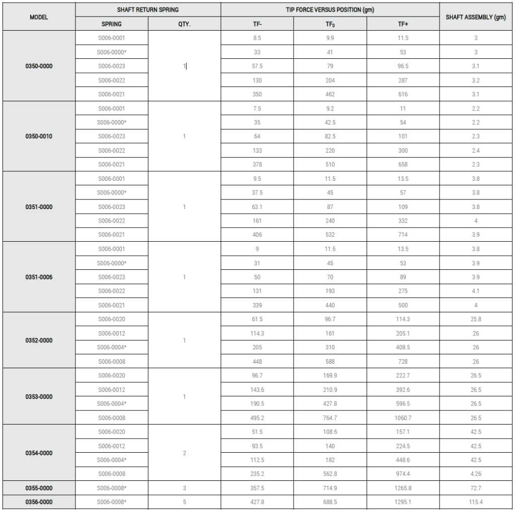
| X0038 | Alternate spring selection (not available for Models 0355-0000 and 0356-0000). See following page for spring model numbers and corresponding tip force. | |
| The following options apply only to Models 0352-0000 through 0356-0000 | ||
| X0013 | Vented housing and LVDT for high pressure applications. | |
| X0014 | Terminate in 7” leads instead of connector. | |
| X0028 | Reverse spring; spring will be in retracted position. | |
| X0029 | Air Purge port for maintaining positive air pressure in the unit. | |
| X0030 | Non-rotating shaft. | |
The standard springs are designated by an asterisk*. The tip force is given for operation within the linear region of the transducer at full extension (TF-), full compression (TF+), and the null position (TF0). The tip forces were determined while the transducer was in the vertical position, pointing down. To determine the tip force when the unit is in a horizontal position, simply subtract the shaft assembly weight from the tip force. To determine the tip force when the unit is vertical, and pointing up, subtract twice the shaft assembly weight. The weight of the shaft assembly includes both the weight of the shaft and the return spring(s). Both the tip forces and the weight of the shaft assembly are given in grams. To convert this value to ounces, divide by 28.38.