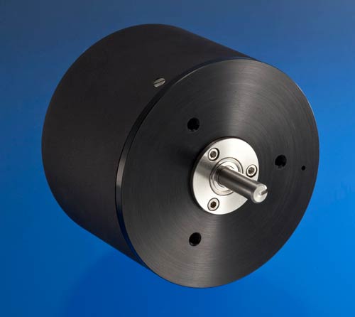
The Series 600 Angular Displacement Transducers (ADT’s) are precision differential capacitors. These transducers do not have the edge effects and dimensional instability characteristic of traditional capacitive devices. The sensing element is coupled to a solid-state oscillator, demodulator, and amplifier to yield DC input – DC output performance.
These transducers deliver a high-level analog DC voltage directly proportional to shaft angular displacement with a high degree of conformity. Rotation is continuous and there is no reactive torque. Reliable performance is assured by the absence of any high-speed rubbing contacts.
| MODEL NO. | DISPL. RANGE +CW, -CCW | LINEARITY* | MAX. USABLE RANGE | LINEARITY USABLE RANGE | OUTPUT VDC | INPUT/ OUTPUT CURVE | TYPICAL TEMP. COEF. SPAN/ °F |
|---|---|---|---|---|---|---|---|
| 0600-0000 | ±30° | ±0.05% | ±40° | ±0.10% | 100 mV/° | 1 | -0.01% |
| 0601-0000 | 10°-70° CW | ±0.05% | 0°-80° CW | ±0.10% | 100 mV/° | 2 | -0.02% |
| 0602-0000 | 10°-70° CCW | ±0.05% | 0°-80° CCW | ±0.10% | 100 mV/° | 3 | -0.01% |
| 0603-0000 | ±60° | ±0.10% | ±80° | ±0.15% | 100 mV/° | 4 | -0.01% |
| 0603-0001 | ±60° | ±0.05% | ±80° | ±0.10% | 100 mV/° | 4 | -0.01% |
| 0603-0002 | 20°-140° CW | ±0.10% | 0°-160° CW | ±0.15% | 50 mV/° | 5 | -0.02% |
| 0603-0003 | 20°-140°CW | ±0.05% | 0°-160° CW | ±0.10% | 50 mV/° | 5 | -0.02% |
| 0603-0004 | 20°-140° CCW | ±0.10% | 0°-160° CCW | ±0.15% | 50 mV/° | 6 | -0.01% |
| 0603-0005 | 20°-140° CCW | ±0.05% | 0°-160° CCW | ±0.10% | 50 mV/° | 6 | -0.01% |
*Definition: Zero Base Terminal Average, expressed as a max % deviation of total range. CW defined as clockwise direction of shaft rotation, when viewed from shaft end.
| REPEATABILITY | < .01% | INTERNAL CARRIER FREQUENCY | 400 KHz | ||
|---|---|---|---|---|---|
| RESOLUTION | Infinite | RIPPLE, MAX. | 20 mV P/P 400 KHz | ||
| CURRENT, INPUT | 30 mA Max. | ZERO ADJUSTMENT | ±3° | ||
| IMPEDANCE, OUTPUT | < 2 Ohms | ZERO POSITIONS | See Output Curves | ||
| MAX. ANGULAR VELOCITY | 1,440°/sec | FREQUENCY RESPONSE | > 1500 Hz | ||
| MAX. ANGULAR VELOCITYwith output down < 2% | 18,000°/sec available(consult factory) | EXCITATION VOLTAGE Input > 18 VDC may damage unit | 15.00 VDC | ||
| INPUT POLARITY PROTECTED | OUTPUT SHORT CIRCUIT PROTECTED | ||||
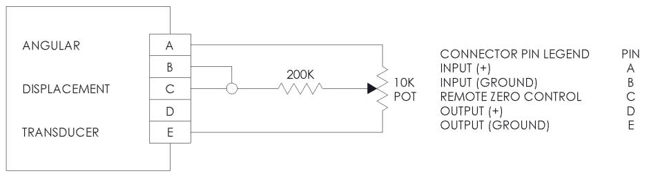
Unless operating in a noise free environment, the lead to pin C must be shielded, as shown. The existing zero adjusted potentiometer in the Angular Displacement Transducer must be rotated fully clockwise before the remote zero control can function correctly. This remote zero control can function correctly. This remote function is useful in applications where it is inconvenient to access the adjustment screw on the transducer housing.
| DISPLACEMENT RANGE | Continuous | NOMINAL WEIGHT | 12.5 oz., 352 gm. |
|---|---|---|---|
| TORQUE, MAX. STARTING(0.5 GM. CM. AVAILABLE) | 5.0 gm. cm. | LIFE: LIMITED BY BEARINGS, EG. | 10 lbs. radial load at 10 RPM; bearing life – 17,000 hours |
| TORQUE, MAX. RUNNING | 3.5 gm. cm. | OPERATING TEMP. RANGE | +32°F to +167°F (0°C to +75°C) |
| MOMENT OF INERTIA, ROTOR | 6 gm. cm.2 | OPERATING TEMP. RANGE (EXPANDED) | -67°F to +257°F (-55°C to +125°C) available (see “Ordering Information”, next pg.) |
| MAX. RADIAL LOAD, AT SHAFT END | 10 lbs. | STORAGE TEMP. RANGE | -67°F to +257°F (-55°C to +125°C) |
| MAX. AXIAL LOAD | 7 lbs. | MOUNTING | Any position, gravity insensitive |
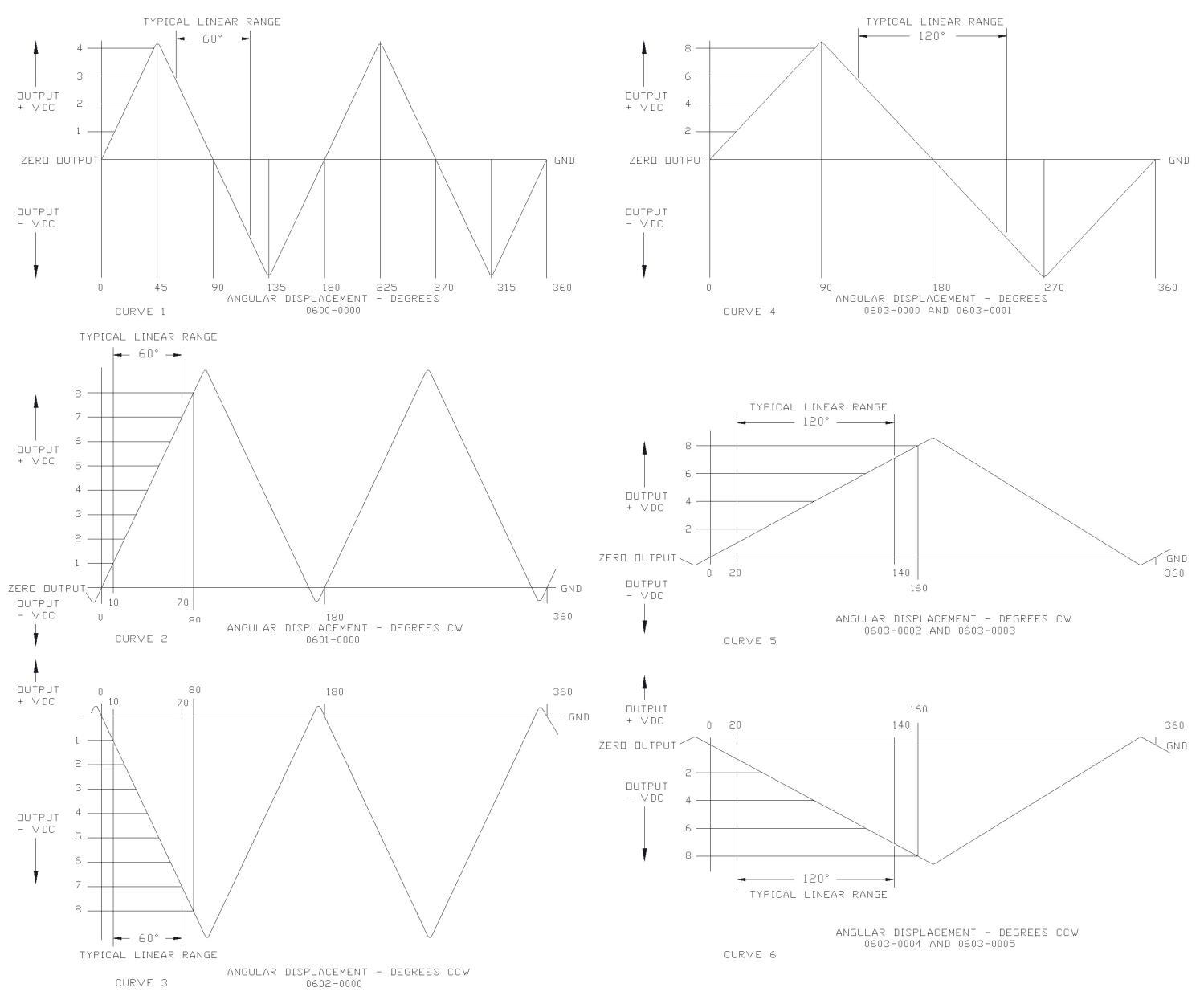
As seen in the output curves graph on the previous page, there is more than one linear range throughout one complete shaft revolution. Only one of these ranges is calibrated. To find the calibrated range, line up the slot in the shaft to the drill hole in the face of the unit. The output voltage at this position corresponds to the angular position within the linear range. For models 0600-0000, 0603-0000, and 0603-0001, this is the zero position.
| MODEL | SLOT-ANGLE POSITION |
|---|---|
| 0600-0000 | 0° ±3° |
| 0601-0000 | 40° CW ±3° |
| 0602-0000 | 40° CCW ±3° |
| 0603-0000, 0603-0001 | 0° ±3° |
| 0603-0002, 0603-0003 | 80° CW ±3° |
| 0603-0004, 0603-0005 | 80° CCW ±3° |
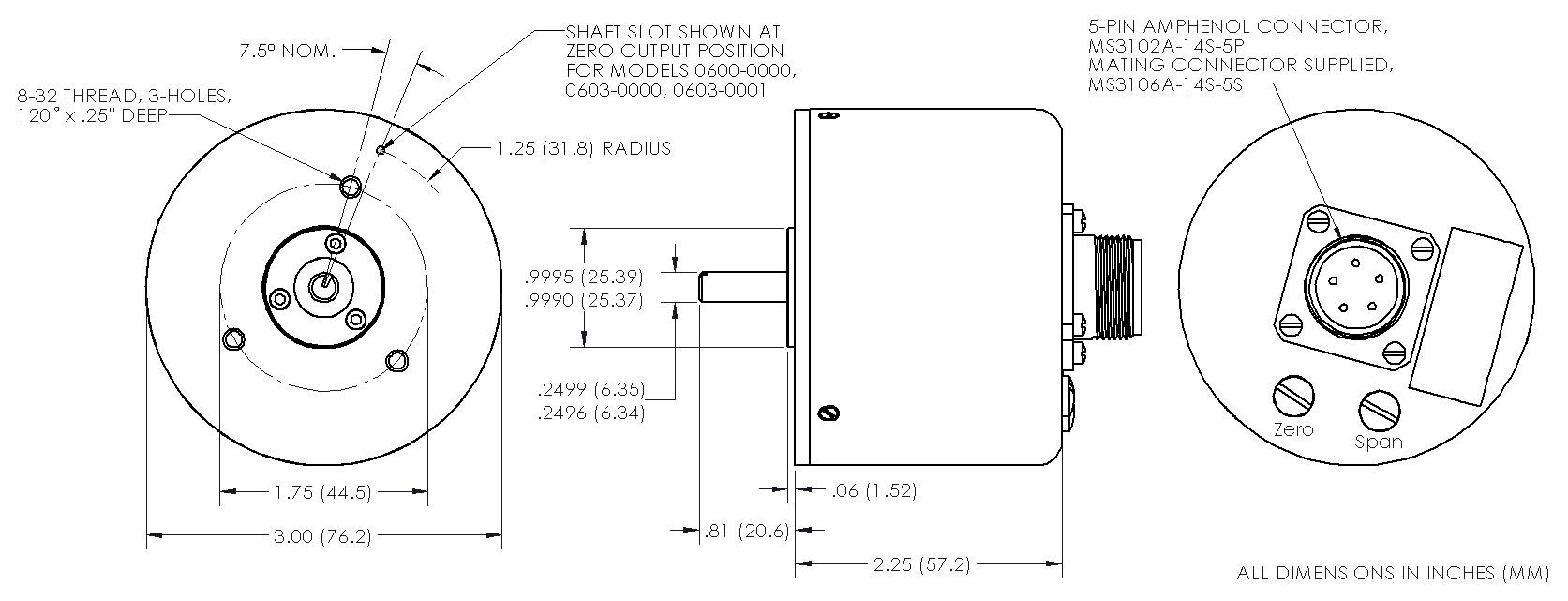
There are no installation restrictions; the transducer can be mounted in any position. Three tapped holes are provided in the mounting surface. The close tolerance stainless steel pilot when fitted into a properly machined bore will predetermine the shaft position. Aligning the shaft slot with the drill spot on the transducer face will approximate the center of the working range. Refer to the dimensional diagram for mounting dimensions.
Notes:
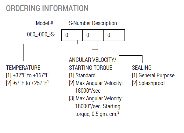
1. When expanded temperature range is selected, option 2 or 3 must be selected under Angular Velocity. Excitation voltage will be limited to 14.2 to 35.0 VDC.
2. The shaft O.D. is reduced to 0.125 inches (3.18 mm).
For an additional charge, the following options are available at the time of purchase:
Units can be factory calibrated to your specified sensitivity; available sensitivity values will vary with the particular model selected, the input voltage and other factors. Please contact factory for details.
Zero offset other than the standard models listed ranging from 0° to ±30° (0600-0000) to 0° to ±60° (0603-0000) can be ordered providing that the maximum output voltage is 8 VDC or less
| OPTION# | DESCRIPTION |
|---|---|
| X0016 | Vibration Protection – Internal electronics are encapsulated in RTV to prevent free movement during high vibration and/or shock |
| X0033 | Material modification for operation in a vacuum environment; Span and Zero pots are replaced by fixed resistors |
| X0035 | Increase axial load tolerance to 14 pounds; not available with high speed option |
| X0042 | Optional side connector configuration; replaces axial connector, see diagram below |