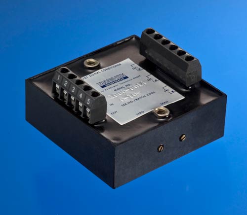
The Series 1000 Oscillator/Demodulators provide complete electrical support for AC LVDTs. Working from an unregulated DC input, the modules generate a stable sinusoidal excitation voltage for the transducer. The LVDT’s secondary voltages are converted into DC voltage by the module’s phase sensitive demodulator. The demodulator has automatic phase synchronization which simplifies installation and setup by eliminating the need to make phase angle adjustments for each transducer. An active, three-pole filter in the final stage reduces output ripple while maximizing frequency response. Other features include zero and span controls, full encapsulation, threaded inserts for mounting, and self-locking terminal strips.
| INPUT POWER | Voltage | ±14.5 to ±28 VDC, Input polarity protected NOTE: DUAL DC OUTPUT POWER SUPPLY REQUIRED |
|---|---|---|
| INPUT POWER | Current | ±150 mA Max. plus LVDT current |
| Voltage | ±14.5 to ±28 VDC, Input polarity protected NOTE: DUAL DC OUTPUT POWER SUPPLY REQUIRED | |
| OSCILLATOR OUTPUT TO LVDT | Voltage | 4.25 to 5.75 VRMS adjustable via 15 turn span control |
| Current | Will drive LVDTs with primary impedance of 100 Ohms or greater. Short circuit and thermally protected | |
| SIGNAL OUTPUT – VOLTAGE | Voltage | DC output is 2 times the RMS output of the LVDT. Output voltage is limited to ±12 VDC. |
| MODELS 1000-0011, 1000-0012, 1000-0014 | Current | ±3 mA without distortion |
| Impedance | Less than 5 Ohms | |
| Ripple | 0.015 VRMS Max. | |
| SIGNAL OUTPUT – CURRENT | Current | 4-20 mA output with LVDT whose sensitivity is 0.5 V/V (±10%). Min. Full Scale Output current: 2-22 mA |
| MODELS 1000-0021, 1000-0022, 1000-0024 | Load Impedance | > 1×10¹⁰ Ohms; Operation into loop impedance between 5 and 400 Ohms. |
| ACCURACY | Non-linearity | ±0.05% Max. over ±10 VDC output |
| Temp. Coef. | < ±0.00025V/°F Zero, < ±0.01% output/°F Span | |
| TEMPERATURE RANGE | Operating | +32 °F to +158°F (0°C to +70°C) |
| Storage | -67 °F to +257°F (-55°C to +125°C) | |
| ZERO ADJUSTMENT | ±0.40 Min. VDC via 15 turn zero control | |
| TERMINAL CONÇNECTIONS | Friction terminals with self locking screws, accepts up to #16 AWG wire. |
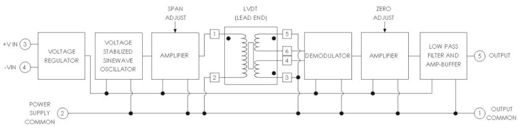
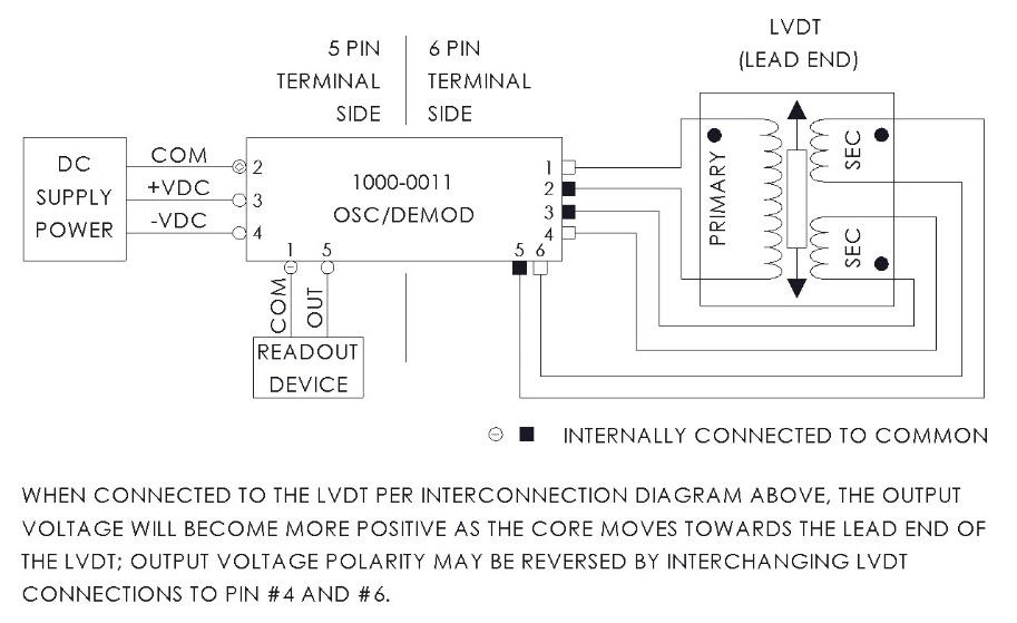
NOTE:
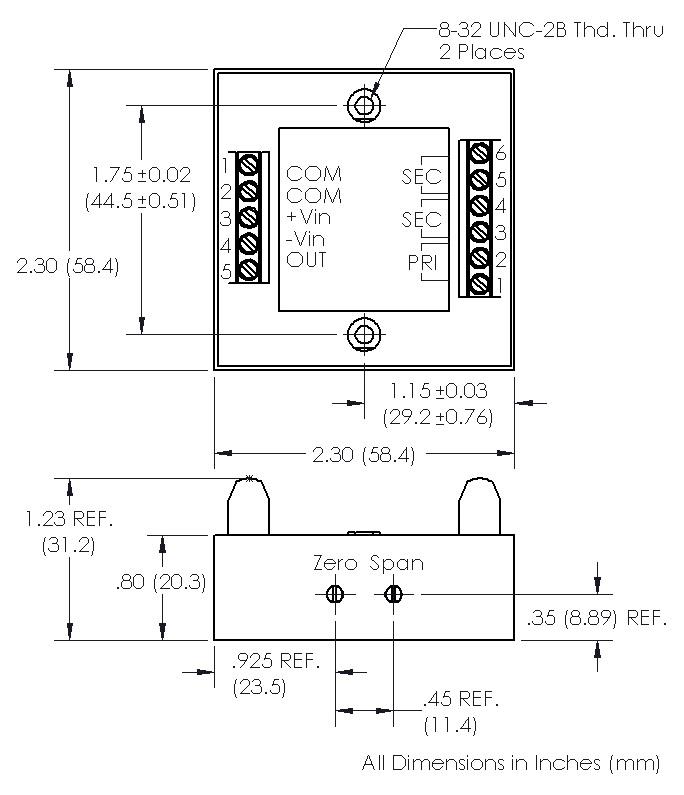
The equivalent models for voltage and 4-20mA output are shown in the table below, along with frequency, phase angle and frequency response for each. All of these modules are physically identical and require the same dual bipolar voltage supply. The output pins 5 and 1 are used for the current output.
| VDC MODEL | 4-20 mA MODEL | FREQUENCY KHz ±10% | LVDT PHASE ANGLE | FREQUENCY RESPONSE, Hz |
|---|---|---|---|---|
| 1000-0011 | 1000-0021 | 3 | ALL | > 500 |
| 1000-0012 | 1000-0022 | 7 | > 10 Degrees | > 1000 |
| 1000-0014 | 1000-0024 | 7 | < 10 Degrees | > 1000 |
| OPTION # | DESCRIPTION |
|---|---|
| X0003 | Provide special zero offset and/or sensitivity |
| X0005 | Provide special cutoff frequency |