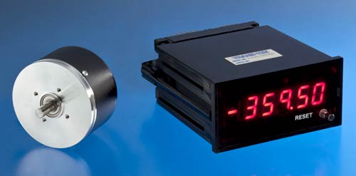
The Model 0607-0002 Optical Encoder and Model 1005-0000 Counter Display system provide precision feedback and readout of shaft angular displacement over the full 360° revolution. From a fixed or user settable point, angular position is displayed in degrees over indefinite shaft revolutions at speeds up to 3000 RPM, with equivalent BCD output, USB output and analog output. In simplest mode, Encoder position is displayed in increments of 0.05° over the range 0.00° to 359.95°. Display and Encoder are sold separately and will deliver full accuracy without adjustment.
Model 0607-0002 is a rotary, incremental Encoder that outputs 1800 cycles of quadrature TTL signal and one zero reference plus (Zr) per shaft revolution. Compact size, low weight, and servo and/or bolt-face mounting make it easy to install, even where space is limited.
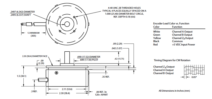
The Encoder’s precision pilot diameter provides a reference for mounting the unit concentric to the shaft to be monitored. Four tapped holes in the face, or the servo slot on its circumference, provide two means for securing the body to the user’s reference surface. Installation of a flexible shaft coupling is highly recommended to protect the Encoder from excessive misalignment or motion of the monitored shaft. Encoder cable can be soldered directly to the Display connector or can be extended.
Model 1005-0000 is a panel mount, 5-digit LED Display that excites the Encoder, decodes its output into 7200 counts/revolution, and displays the shaft angle position-in increments of 0.05°-from the last reset. It also provides latchable, strobed BCD output that matches the displayed value.
The compact 1/8 DIN case, rear-panel set-up and solder termination make it easy to install, even where space is limited. The Display installs directly through panels up to 0.25 inch (6.35 mm) thick, or can be used as a benchtop instrument. All necessary mating D-SUB connectors are included, to which Encoder leads, 12 VDC power and any other required connections can be soldered directly.
The meter also includes an analog output, providing +/-5.0 VDC over the range +/-359.95°, and a USB output that provides display data and remote reset operation.
When installed, the Encoder body is typically secured to the reference surface and its shaft is fixed (preferably by a flexible coupling) to the shaft being monitored. Its leads are connected to the Display, which requires a 12 VDC external power source that can provide at least 450 mA of current. The Display can be programmed, either locally or remotely, by electrically shorting the proper pins (ref. jumpers F1, F2, etc.) at its connector. The Display reads directly in degrees and resets to 000.00° at each of the following: 1) at power-up; 2) anytime it reaches 360.00° (regardless of sign); 3) when the front panel RESET button is pressed; 4) when F1 is closed for at least 0.01 seconds; and 5) at ZR, only when F2 is closed. The Display is shipped with the following contacts open: F1, F2, F3 and F4. In this configuration, the display range is -359.95° to +359.95° and the displayed value increases while rotating the shaft in a clockwise direction (as viewed from the end of the shaft, looking towards the body). Closing F2 enables the reset at ZR . Closing F3 changes the sense of the display to counterclockwise. Closing F4 changes the display range to 000.00° to 359.95°.
| ELECTRICAL | ||
|---|---|---|
| Resolution Range | 1800 cycles per revolution (7200 counts per revolution with external 4X counting when using A and B channel outputs) | |
| Light Source | LED | |
| Light Sensor | Photodiode | |
| Excitation | 5 VDC ±10%, 80 mA | |
| Output Format | Two counts channel outputs (A and B) in phase quadrature, plus zero reference ZR; all are TTL single ended square waves with rise and fall time of one microsecond maximum into 1000 pF load | |
| ZR Reference | Full cycle | |
| Frequency Response | Up to 100 kHz, all channels | |
| Phase Sense | Channel A leads B for CW rotation of shaft (as viewed from shaft end, looking towards body) | |
| Termination | Shielded cable with #24 AWG lead wires (see diagram below for lead color vs. function) | |
| MECHANICAL | ||
|---|---|---|
| Shaft Loading | 10 lb axially and radially, maximum; 100,000 radians/sec2 maximum angular acceleration | |
| Shaft Radial Runout | 0.001 inch (.025mm) T.I.R. | |
| Bearing | R-4 shielded; 0.1 ounce-inch (7.2 gram-cm) | |
| maximum starting torque at 25°C | ||
| Operating Speed | 3000 RPM maximum continuous | |
| Materials | 303 stainless steel shaft; aluminum pilot diameter and base; anodized aluminum cover | |
| Weight | 5 ounces (142 grams) | |
| ENVIRONMENTAL | ||
| Temperature | -23°F to 158°F (-10°C to 70°C) Operating | |
| -31°F to 176°F (-35°C to 80°C) Storage | ||
| Shock | 30 G’s for 11 milliseconds maximum | |
| Vibration | 50 Hz, 10 G’s for 1 hour | |
| Humidity | To 98% R.H. (non-condensing) | |
| ELECTRICAL | ||
|---|---|---|
| Resolution Range | 0.05 count over range -359.95 to +359.95 | |
| Display Type | 0.5 inch (12.7 mm) high red LEDs; 5 digits plus ± sign and decimal point | |
| Excitation | 12 VDC ±10%, 400 mA maximum | |
| Signal Inputs | Accepts TTL level single-ended A, B, ZR inputs; with A and B input count is multiplied by four; the inputs pass through a single pole noise filter rolled off at 100 kHz | |
| Output Signal | Latchable, TTL BCD outputs that correspond to the displayed value. Analog output ±5.0 VDC over ±359.95°. USB output providing display data. | |
| Selectable | Closing F1 resets display to 000.00 Closing F2 enables reset at ZR Closing F3 changes sense to CCW Closing F4A/B selects range 000.00 – 359.95 | |
| Set-up Features | ||
| MECHANICAL | ||
|---|---|---|
| DIMENSIONS | INCHES (mm) | |
| Case Size (H x W x L) | 1.72 (44) x 3.56 (90) x 6.1 (156) | |
| Front Panel (H x W x L) | 1.91 (49) x 3.80 (97) x 0.1 (3) | |
| Cut Out (H x W) | 1.77 (45) x 3.62 (92) | |
| Max. Panel Thickness | 0.25 (6.35) | |
| Termination | Two rear panel 15-pin D-SUB connectors with solder lugs and USB-A Port | |
| ENVIRONMENTAL | ||
| Temperature | 32°F to 131°F (0°C to 55°C) Operating 14°F to 140°F (-10°C to 60°C) Storage | |
| ELECTRICAL | ||
|---|---|---|
| Resolution Range | 0.05 count over range -359.95 to +359.95 | |
| Display Type | 0.5 inch (12.7 mm) high red LEDs; 5 digits plus ± sign and decimal point | |
| Excitation | 12 VDC ±10%, 400 mA maximum | |
| Signal Inputs | Accepts TTL level single-ended A, B, ZR inputs; with A and B input count is multiplied by four; the inputs pass through a single pole noise filter rolled off at 100 kHz | |
| Output Signal | Latchable, TTL BCD outputs that correspond to the displayed value. Analog output ±5.0 VDC over ±359.95°. USB output providing display data. | |
| Selectable | Closing F1 resets display to 000.00 Closing F2 enables reset at ZR Closing F3 changes sense to CCW Closing F4A/B selects range 000.00 – 359.95 | |
| Set-up Features | ||
| MECHANICAL | ||
|---|---|---|
| DIMENSIONS | INCHES (mm) | |
| Case Size (H x W x L) | 1.72 (44) x 3.56 (90) x 6.1 (156) | |
| Front Panel (H x W x L) | 1.91 (49) x 3.80 (97) x 0.1 (3) | |
| Cut Out (H x W) | 1.77 (45) x 3.62 (92) | |
| Max. Panel Thickness | 0.25 (6.35) | |
| Termination | Two rear panel 15-pin D-SUB connectors with solder lugs and USB-A Port | |
| ENVIRONMENTAL | ||
| Temperature | 32°F to 131°F (0°C to 55°C) Operating 14°F to 140°F (-10°C to 60°C) Storage | |
NOTE: Display latch is enabled with logic “1” and must be tied to ground (logic low “0”) for normal operation.
Lower Nibble holds D0, D1 and D3 BCD data. Upper Nibble holds D2 and D4 BCD data. Pol(+) stored in Upper Nibble.
Output Enable and BCD Latch is enabled with logic “0”.
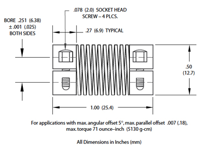
| F001-0019 | Flexible Shaft Coupling – (see dimensional diagram above) |
|---|---|
| C000-0008 | Connector – when ordered on Encoder, leads are terminated in type MS3106A-14S-5P connector (Red lead to Pin A; White to B; Black to C; Yellow to D; Green to E) |
| F001-F019 | Flexible Shaft Coupling - (see dimensional diagram above) |
| C000-0046 | Cable – vinyl jacketed, 15 ft. long, terminated at one end in type MS3101A-14S-5S connector (mates with C003-0008) and leads at other end (Pin A to Red lead; B to Blue; C to Black; D to Brown; E to White; N/C to Green); operating temperature for Cable is -22°F to +176°F (-30°C to +80°C) |
| 1100-0002 | Line Powered Supply – 80-264 VAC input, 12 VDC output, 8W – 12.0 VDC ±5% at current up to 0.66 Ampere; 47-63 Hz input; operating temperature 32°F to 104°F (0°C to 40°C), storage temperature -4°F to 140°F (-20°C to 60°C); with 2-prong North American line plug, U.K style 3-prong plug or 2-prong E.U. style plug options; terminated in 5.5mm OD x 2.5 mm ID x 11.0mm Barrel Plug. Each 1005- meter comes with a power supply, for replacement reference this part number. |