- Core Extension Rods
- Mounting Clamps
- Model 1003

The Series 200 DC-DC LVDTs are precision Linear Variable Differential Transformers packaged with a solid state oscillator and a phase sensitive demodulator. The transducer is designed to work with DC voltages, and has excellent linearity, infinite resolution, and high sensitivity. Input and output circuits are electrically isolated from each other and from the coil assembly housing, making them usable directly in floating or ground return systems. DC indicators, recorders, and control systems can usually be driven directly by the large DC output. The core, when displaced axially within the coil assembly, produces a voltage change in the output directly proportional to the displacement.
| ODEL NUMBER | 0240-0000 | 0241-0000 | 0242-0000 | 0243-0000 | 0244-0000 | 0245-0000 | 0246-0000 | 0246-00005 | ||||||||
|---|---|---|---|---|---|---|---|---|---|---|---|---|---|---|---|---|
| WORKING RANGE, ± Inches (mm) | 0.050 (1.27) | 0.100 (2.54) | 0.250 (6.35) | 0.500 (12.7) | 1.00 (25.4) | 2.00 (50.8) | 3.00 (76.2) | 3.00 (76.2) | ||||||||
| MAX. USABLE RANGE, ± Inches (mm) | 0.075 (1.78) | 0.150 (3.75) | 0.375 (9.53) | 0.750 (19.1) | 1.50 (38.1) | 2.75 (69.8) | 3.25 (82.5) | 4.00 (101) | ||||||||
| INPUT, VDC | 6.0 Min. to 30 Max. | 9.0 Min. to 30 Max. | ||||||||||||||
| NOMINAL F.S. OUTPUT, ±VDC with unloaded output | ||||||||||||||||
| @ 6 VOLT INPUT | 1.3 | 2.4 | 1.8 | 3.1 | 4.6 | 3.9 | 3.3 | N/A | ||||||||
| @ 15 VOLT INPUT | 3.4 | 6.4 | 4.8 | 8.3 | 12.1 | 10.2 | 8.7 | 10 | ||||||||
| @ 24 VOLT INPUT | 5.5 | 10.4 | 7.8 | 13.5 | 18.7 | 16.5 | 14.1 | 16.3 | ||||||||
| @ 30 VOLT INPUT | 7 | 13 | 9.7 | 17 | 24.8 | 20.7 | 17.7 | 30.5 | ||||||||
| INPUT CURRENT | 8.3 mA @ 6 Volt input to 52 mA @ 30 Volt input | |||||||||||||||
| 2 NON-LINEARITY | ±0.5% Full Scale Over Total Working Range, ±1.0% Full Scale Over Maximum Usable Range | |||||||||||||||
| INTERNAL CARRIER FREQUENCY, Hz | 13000 | 12000 | 3600 | 3400 | 3200 | 1500 | 1400 | 1400 | ||||||||
| % RIPPLE, RMS (nominal) | 0.7 | 0.7 | 0.8 | 0.8 | 0.8 | 1 | 1 | 1 | ||||||||
| OUTPUT IMPEDANCE, Ohms | 2500 | 3500 | 5200 | 5500 | 5600 | 5500 | 5600 | 5600 | ||||||||
| FREQ. RESPONSE (3 dB down), Hz | 300 | 140 | 115 | 110 | 100 | 110 | 75 | 75 | ||||||||
| TEMPERATURE RANGE | -65°F to +250°F (-54°C to +121°C) | |||||||||||||||
| RESOLUTION | Infinite | |||||||||||||||
Notes:

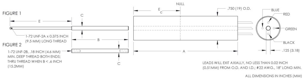
| MODEL* | LINEAR RANGE | BODY LENGTH, A | ELECTRICAL CENTER, Ec | BODY MASS | CORE LENGTH, B | EXTENSION LENGTH, E |
|---|---|---|---|---|---|---|
| ±Inches (mm) | Inches (mm) | Inches (mm) | Grams | Inches (mm) | Inches (mm) | |
| 0240-0000__ | 0.05 (1.27) | 0.87 (22.1) | 0.34 (8.64) | 55.8 | 0.56 (14.2) | 1.9 (48.3) |
| 0241-0000__ | 0.10 (2.54) | 1.12 (28.5) | 0.46 (11.7) | 59.2 | 0.75 (19.1) | 1.9 (48.3) |
| 0242-0000__ | 0.25 (6.35) | 3.21 (81.5) | 1.44 (36.6) | 121.4 | 1.75 (44.5) | 1.9 (48.3) |
| 0243-0000__ | 0.50 (12.7) | 3.71 (94.2) | 1.69 (42.9) | 132.2 | 1.87 (47.5) | 2.4 (60.9) |
| 0244-0000__ | 1.00 (25.4) | 4.71 (120) | 2.19 (55.6) | 156.2 | 2.00 (50.8) | 3.2 (81.2) |
| 0245-0000__ | 2.00 (50.8) | 8.21 (209) | 3.94 (100) | 235.4 | 3.50 (88.9) | 5.2 (132) |
| 0246-0000__ | 3.00 (76.2) | 10.52 (267) | 5.09 (129) | 293 | 3.50 (88.9) | 8.4 (213) |
| 0246-00005 | 4.00 (101.6) | 10.52 (267) | 5.09 (129) | 293 | 2.00 (50.8) | 9.1 (231) |
* Model numbers ending with a “_” have multiple core options. All standard units will end with a 0 indicating a core assembly. This core assembly consists of a core brazed to an extension rod that terminates in 1-72 UNF-2A threads. If an option is not selected, option 0 will be provided. Option 1 indicates a core assembly with a smaller core. Core options 2 and 3 provide a threaded core only. A separate extension rod can be used to connect the core to the moving object.
| Core Assembly Ref Fig. 1 | Threaded Core Ref Fig. 2 | |||||
|---|---|---|---|---|---|---|
| OPTION 0 | OPTION 1 | OPTION 2 | OPTION 3 | |||
| MODEL | C = 0.120*(3.05mm) | C = 0.099*(2.51mm) | C = 0.120*(3.05mm) | C = 0.099*(2.51mm) | ||
| 0240-0000_ | C004-0000 | C004-0001 | C005-0002 | C005-0003 | ||
| 0241-0000_ | C004-0198 | C004-0199 | C005-0153 | C005-0154 | ||
| 0242-0000_ | C004-0010 | C004-0006 | C005-0054 | C005-0051 | ||
| 0243-0000_ | C004-0011 | C004-0007 | C005-0035 | C005-0023 | ||
| 0244-0000_ | C004-0012 | C004-0008 | C005-0048 | C005-0052 | ||
| 0245-0000_ | C004-0013 | C004-0009 | C005-0053 | C005-0033 | ||
| 0246-0000_ | C004-0014 | C004-0015 | C005-0053 | C005-0033 | ||
| 0246-00005 | C004-0057 | N/A | N/A | N/A | ||
The core is constructed from a soft, high permeability iron-nickel alloy. Nonmagnetic stainless steel is used as extension rod material. Core assemblies are sized for use over the maximum working range of the LVDT. The difference between option 0 and 1 is the core outer diameter. Smaller O.D. cores should be considered for applications with some radial movement to prevent contacting the inner diameter of the coils. The smaller core diameter will decrease sensitivity slightly (< 5%).
Options 2 and 3 are cores only, tapped at both ends with 1-72 UNF-2B threads, as shown in Figure 2 of the Dimensional Drawing. These should be used in applications when a separate extension rod is desirable. The difference between option 2 and 3 is the outer diameter.
The model 0246-00005 has only one core assembly available. This unit is designed to operate over the maximum usable stroke of ±4.0 inches (±102mm).
The high pressure version of the Series 240 is suitable for operation in nonconductive and noncorrosive fluids or gasses at pressures up to 5000 P.S.I. The vented housing eliminates pressure differentials between the environment and the transducer’s interior, allowing rapid and extreme pressure changes without damage or degradation in performance.
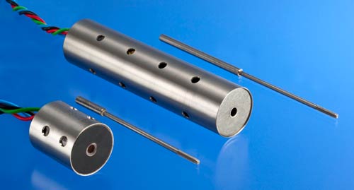
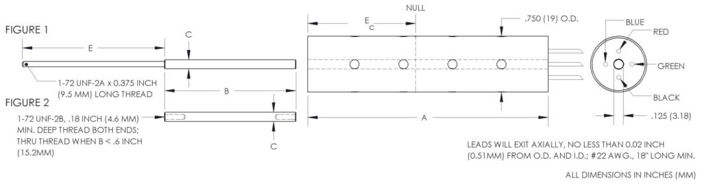
Note: All electrical and physical specifications are the same as the standard Series 240 LVDTs
| MODEL* | STROKE, ±INCHES (MM) |
|---|---|
| 0240-0008_ | 0.05 (1.27) |
| 0241-0007_ | 0.10 (2.54) |
| 0242-0006_ | 0.25 (6.35) |
| 0243-0009_ | 0.50 (12.7) |
| 0244-0014_ | 1.00 (25.4) |
| 0245-0007_ | 2.00 (50.8) |
| 0246-0008_ | 3.00 (76.2) |
* Model numbers ending with a “_” have multiple core options. All standard units will end with a 0 indicating a core assembly. This core assembly consists of a core brazed to an extension rod that terminates in 1-72 UNF-2A threads. If an option is not selected, option 0 will be provided.
| OPTION# | DESCRIPTION |
|---|---|
| X0001 | Splashproof – protects the unit from washdown environments or outdoor applications by means of an additional washer on the non-lead end. Applies to Models 0242-0000_ through 0246-0000_ |
| X0004 | Modify length of the extension rod to user specified length; specify as Dimension E |
| X0007 | Provide maximum non-linearity of ±0.25% full scale |
| X0010 | Cable termination; eight feet of 4 conductor, #22 AWG., PVC cable; temperature range changes to 0°F to 175°F (-17°C to +79°C) |
| X0011 | Provide an offset and scaled output voltage; special connector and mating connector included; used only with load impedances of 1 Megohm or greater; input voltage and scaling parameters must be specified |
| X0023 | Install second brazed extension rod |
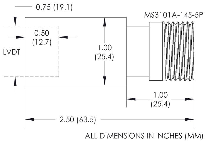
| X0025 | Terminate in an integral connector type MS3101A-14S-5P; adaptor for connector has 1.00” O.D.; includes mating connector |
| X0036 | Welded non-lead end for enhanced splashproofing; applies to Models 0242-0000_ through 0246-0000_ |
| X0040 | Cable termination – extended temperature range; eight feet of 4 conductor, #22 AWG., Teflon cable; temperature range increased to -65°F to +250°F (-55°C to +121°C) |
For more detailed information about these options, please contact the factory.