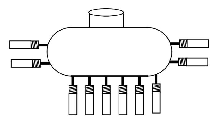
Gaging LVDTs Test Gasoline Tank Expansion

Trans-Tek gaging transducers offer precision linear feedback in a spring-loaded package, often replacing the more common free-unguided LVDTs where the object being measured can not support a direct connection to the core assembly. The Series 310-320 AC-style gaging transducer covers long-stroke requirements ranging from ±0.25” to ±10.0”. Each model in this group uses the Series 210-220 LVDT as part of its construction. For example, the Model 0215-0000 is used to make the Model 0315-0000. As a result, the Series 310-320 features the same performance advantages as our AC-AC LVDTs: exceptional linearity, temperature coefficient, and resolution.
The Series 310-320 is assembled using high-quality springs, fitted to a shaft containment/guidance mechanism. The springs were selected for optimal balance between mechanical frequency response and contact tip force. The internal LVDT is mounted in series with the spring, which is positioned over the shaft of the core assembly. The spring is contained at one end by the LVDT and by a mechanical stop near the tip end. The shaft is guided through a linear bearing. The outer housing features 3/4” external threading for securing to the end-user’s fixture. A removable contact tip is screwed onto the shaft end and each model terminates in a 5-pin MS-style connector. All mating connectors and cable assemblies are sold separately.
Over the years, a frequent application using our spring-loaded LVDTs is tank expansion testing. Cycle life testing is often done by automobile manufacturers to check the structural durability of gasoline tanks under various conditions. Recently, several pieces of a modified Model 0318-0000 were purchased for exactly this purpose.
This special unit – the Model 0318-0001 – was chosen for its overall shorter length than the standard Model 0318. Because of sizing constraints in the test chamber, the fully extended length of 13.4” was an easier fit than the 22.5” length of the standard version. Several transducers were positioned around the tank, usually three placed on top pointing downward and three on the bottom pointing upward. Expansion of the tank walls exerted a force on the transducer’s shaft tip causing a deflection. To simulate wall movement as experienced by most vehicle gas tanks, air pressure was applied to cause expansion, followed by a vacuum to contract the walls a similar amount. Conditions around the tank – especially temperatures – were changed frequently to simulate environmental conditions. After long cycling periods, all wall surfaces were carefully examined for any visible stress fractures or signs of strain.
Another area of concern was the explosive properties represented by the gasoline stored in the tank during testing. All electrical equipment – including the gaging transducers – were carefully chosen with this potentially serious danger in mind. Extra was taken by adding an air inlet tube at the back end of the transducer. At all times during testing, an air purge line was attached to this inlet, allowing a constant air stream to pass through the inside of the unit and out the front end. This added feature prevented any combustible fumes or particulars from getting inside the LVDT.
The physical capabilities of our gaging transducers – measurement without a hard connection to the core assembly – were essential in fulfilling this auto maker’s testing requirements. Trans-Tek’s flexibility in providing added modifications made it a perfect fit.