There is a direct relationship between the load impedance, DC resistance of the coils, and frequency response in the transducers. The DC resistance of the coils is given as “R” in the specifications. There are two frequency response values listed for specific load impedance levels: one at “10R” and the other at “100R”. If the load resistance falls between these two values, a linear relationship can be assumed. Load impedances above “100R” will improve the response rate up to a certain level, and then plateau.
For load impedances below “10R”, however, there is a significant impact on the operation of the LVT. The following formulas will enable the user to compute: the constant velocity output voltage, the attenuation due to a sinusoidally varying voltage, or the phase shift of the output voltage versus the input velocity.
| R | DC Resistance of the coils in Series |
| RL | Load Impedance |
| F | Frequency of Sinusoidal Motion |
| L | Inductance of Coils |
| V | Output voltage with “no load” |
| VL | Output voltage with “load” |
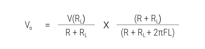
To determine the output voltage across a load < 10R:
To determine the angular phase shift of output voltage versus sinusoidally varying velocity:

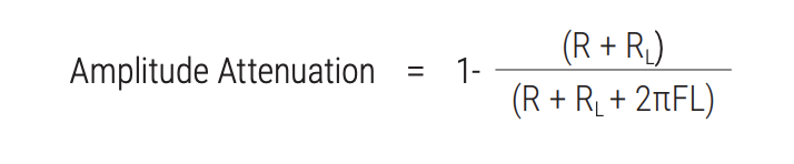
To determine amplitude attenuation of a sinusoidal motion due to frequency: