Series 200
Short Stroke DC LVDTs
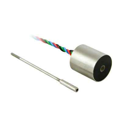
The Series 200 DC-DC LVDTs are precision Linear Variable Differential Transformers packaged with a solid state oscillator and a phase sensitive demodulator. The transducer is designed to work with DC voltages, and has excellent linearity, infinite resolution, and high sensitivity. Input and output circuits are electrically isolated from each other and from the coil assembly housing, making them usable directly in floating or ground return systems. DC indicators, recorders, and control systems can usually be driven directly by the large DC output. The core, when displaced axially within the coil assembly, produces a voltage change in the output directly proportional to the displacement.

Key Features
- Ranges from ±0.05” to 0.20”
- High Sensitivity
- Non-linearity < 0.5%, 0.3%
- Stainless Steel Construction
SPECIFICATIONS - ELECTRICAL
| MODEL | 0200-00000 | 0200-00010 | 0201-00000 | 0201-00010 |
| RANGE, ±Inches (±mm) | 0.050(1.27) | 0.50 (1.27) | 0.100 (2.54) | 0.100(2.54) |
| INPUT, VDC | 7 Max, 5 Min | |||
| INPUT, mA | 20 | 20 | 35 | 35 |
| OUTPUT, FULL SCALE OPEN CIRCUIT, ±VDC | 1.5 | 1.5 | 2.8 | 2.8 |
| LINEARITY, ±FULL SCALE, % | 0.5 | 0.3 | 0.5 | 0.3 |
| INTERNAL CARRIER FREQUENCY | 9KHz | |||
| MAX RIPPLE, RMS/VDC Output Range | 0.7% | |||
| OUTPUT IMPEDANCE, KOhms | 2.2 | 2.2 | 3.0 | 3.0 |
| FREQ. RESPONSE (3 dB down), Hz | 350 | 350 | 170 | 170 |
| TEMPERATURE RANGE | -65°F to +140°F (-54°C to +60°C) | |||
| RESOLUTION | Infinite | |||
Notes:
- Polarity of excitation must be observed for proper function. Reversal will not damage the unit.
- Load Impedance of 50 KOhms minimum required for proper operation.
- Output polarity will be positive on one side of null, negative on the other side of null.
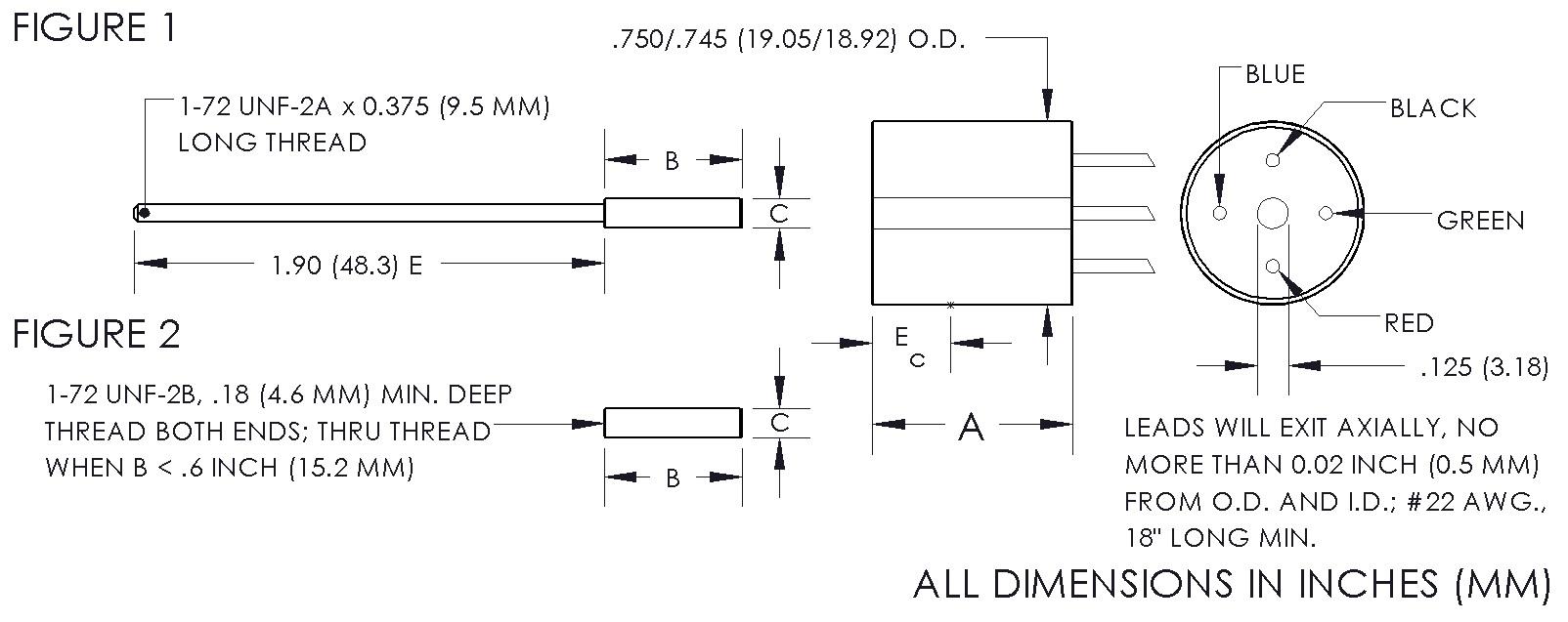
- Blue lead is more positive with respect to the Green lead when the core is moved toward the lead end.
SPECIFICATIONS - MECHANICAL
| MODEL* | LINEAR RANGE ±Inches (mm) |
BODY LENGTH, A Inches (mm) |
ELECTRICAL CENTER, Ec Inches (mm) |
BODY MASS Grams |
CORE LENGTH, B Inches (mm) |
EXTENSION LENGTH, E Inches (mm) |
| 0200-0000__ | 0.05 (1.27) | 0.81 (20.6) | 0.32 (8.13) | 21 | 0.56 (14.2) | 1.9 (48.3) |
| 0200-0001__ | 0.05 (1.27) | 0.81(20.6) | 0.32 (8.13) | 21 | 0.56 (14.2) | 1.9 (48.3) |
| 0201-0000__ | 0.10 (2.54) | 1.06 (26.9) | 0.44 (11.2) | 26 | 0.81 (20.6) | 1.9 (48.3) |
| 0201-0001__ | 0.10 (2.54) | 1.06 (26.9) | 0.44 (11.2) | 26 | 0.81 (20.6) | 1.9 (48.3) |
* Model numbers ending with a “_” have multiple core options. All standard units will end with a 0 indicating a core assembly. This core assembly consists of a core brazed to an extension rod that terminates in 1-72 UNF-2A threads. If an option is not selected, option 0 will be provided. Option 1 indicates a core assembly with a smaller core. Core options 2 and 3 provide a threaded core only. A separate extension rod can be used to connect the core to the moving object.
DIMENSIONAL DIAGRAM
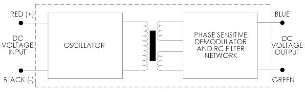
BLOCK DIAGRAM
CORE OPTIONS
| Core Assembly Ref Fig. 1 | Threaded Core Ref Fig. 2 | |||
| OPTION 0 | OPTION 1 | OPTION 2 | OPTION 3 | |
| MODEL | C = 0.120″ (3.05mm) |
C = 0.099″ (2.51mm) |
C = 0.120″ (3.05mm) |
C = 0.099″ (2.51mm) |
| 0200-0000__ | C004-0000 | C004-0001 | C005-0002 | C005-0003 |
| 0200-0001__ | C004-0000 | C004-0001 | C005-0002 | C005-0003 |
| 0201-0000__ | C004-0002 | C004-0003 | C005-0006 | C005-0007 |
| 0201-0001__ | C004-0002 | C004-0003 | C005-0006 | C005-0007 |
* Model numbers ending with a “_” have multiple core options. All standard units will end with a 0 indicating a core assembly. This core assembly consists of a core brazed to an extension rod that terminates in 1-72 UNF-2A threads. If an option is not selected, option 0 will be provided. Option 1 indicates a core assembly with a smaller core. Core options 2 and 3 provide a threaded core only. A separate extension rod can be used to connect the core to the moving object.
SALE OPTIONS
| Option# | Description |
| X0002 | Splashproof – protects the unit from washdown environments or outdoor applications |
| X0004 | Modify length of the extension rod from 1.9” to user specified length; specify as Dimension E |
| X0010 | Option cable termination; eight feet of 4 conductor, 22 AWG, PVC cable |
| X0011 | Provide an offset and scaled output voltage; special connector and mating connector included; used only with load impedances of 1 Megaohm or greater; input voltage and scaling parameters must be specified |
| X0017 | Modify unit for use in any noncorrosive, nonconductive medium, such as hydraulic fluid, for pressure < 5000 PSI; housing is vented |
| X0023 | Install second brazed extension rod to user specified length; specify as Dimension E |
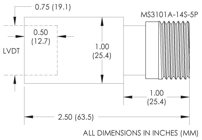
| X0025 | Optional MS-style connector termination. Increases O.D. to 1.00”; mating connector supplied |
| X0040 | Optional cable termination; eight feet of 4 conductor, 22 AWG, Teflon cable; temperature range increased to -65°F to +250°F (-55°C to +121°C) |
OPTION X0025
CAD Drawings
Download drawings from 3DContentCentral.com. (Account Required)
RELATED PRODUCTS AND ACCESSORIES
- Core Extension Rods